Upcoming Events:
Error 406 - Not Acceptable
Generally a 406 error is caused because a request has been blocked by Mod Security. If you believe that your request has been blocked by mistake please contact the web site owner.
Full event list
Error 406 - Not Acceptable
Generally a 406 error is caused because a request has been blocked by Mod Security. If you believe that your request has been blocked by mistake please contact the web site owner.
FIRST® Robotics Competition (FRC®)
Control System 2000-2003
Prior to 2000 the control system used for the FIRST Robotics Competition (FRC) was loaned to teams and had to be returned
at the end of each season. Then FIRST began giving teams controllers to keep and our robots could be kept running for years,
giving rise to off-season competitions, pre-season robot practice, community demonstrations, etc. These controllers can be
used for basic operation of any robot and have continued to be useful for years as control systems for practice and experimental robots.
The 2003 FIRST Robotics Competition (FRC) control system had a smaller, mini-robot cousin (called Edu) designed and manufacturered by
Innovation First Inc. (IFI). It was available to educate teams on the basics of robotics and to develop software that ported quite easily to the
full-sized robot controller and to prototype simple mechanical design concepts.
Control System Components
This control system had two similar looking main components:
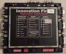
-- An Operator Interface (OI) that joysticks plugged into and that in turn plugged into the FIRST arena control system at the driver's station. Based on a PIC16F877 microcontroller.
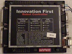
-- A Robot Controller (RC) that resided on the robot and controlled all the motor and solenoid actions. Also designed around a master PIC16 microcontroller, which controlled the I/O to enforce overriding field control. It also had a second user programmable processor, a Parallax Basic Stamp 2SX that we were able to program to have the robot do what we wanted in Parallax pBasic.
The two communicated via radio modem or by a standard serial cable used as a tether connection.
This OI could easily be mistaken for later version OI's up to 2008, however, pre-2004 OI's are not interchangable with 2004-2008 OI's and do not work with newer RC's.
Robot Controller

Different years used gradually upgraded Parallax Basic Stamp processors.
Processor Specs. BASIC Stamp 2sx (used in 2003):
- Processor Speed 50 MHz
- Program Execution Speed ~10,000 instuctions/sec.
- RAM Size 32 Bytes (6 I/O, 26 Variable)
- Scratch Pad RAM 64 Bytes
- EEPROM (Program) 8 banks of 2K Bytes each, ~4,000 instructions
- Number of I/O pins 16 +2 Dedicated Serial
- PC Programming Interface Serial Port (9600 baud)
This is built on a Parallax Basic Stamp and is user programable in Parallax pBasic. 2003 used the BS2sx processor. The RC has two duplicate memory banks, selectable by a physical jumper, where separate programs can be loaded. This simply allows two different (or the same) programs to be loaded and the user can switch between them by moving a suitcase jumper on the board. Within each program memory space there are eight (8) banks that the program can dynamically switch control between. For instance, Bank 0 could have your initialization code, that passes control over to Bank 1 to run the tele-operated code. Banks 2-7 might be used for various special processing, such as, the autonomous period that debuted in 2003. A fixed amount of writeable memory is shared between these program banks, so it is easy to pass information between banks, however, the programmer must plan carefully to avoid overwriting and corrupting memory addresses that another bank might be using.
The RC has several external protective fuses and indicator LEDs that tell if any had been blown.
Digital I/O connections and Analog input connections were made via 25-pin sub-D connectors the user had to construct their own wiring for. Relay outputs to Spike relays for pneumatic solenoids or fwd/neutral/rev motors are via .1" pin headers.
Team numbers were set on both the OI and RC via DIP switches and there are 9-pin serial cable connectors for programming, tether, and radio modem.
Operator Interface
 This general Operator Interface (OI) design was kept even when the RC had a major change over in 2004 to a Microchip PIC processor, however, there
are some differences that prevent a pre-2004 OI from working with a 2004 and later RC.
There are several protective fuses, resets for both the remote RC and local OI, radio channel selection DIP switch, Team number DIP switch, etc.
The layout provides connections for:
- Four (4) joystick gameport connections or custom wiring by the user
- A dashboard port a desktop or laptop computer can be hooked to to receive and display basic controller information
- A radio modem port (RS-422)
- A tether port (standard serial cable)
- A Competition port to hook to the FIRST arena control system or to enable/disable the robot, to engage autonomus, and to enable different radio channels.
Radio Modem
The OI and RC communicate via tether cable or by a pair of radio modems such as these. This basic type of radio modem is compatable with the OI/RC across years and with work equally well with the 2000-2003 control systems as with the 2004-2008 control systems. One modem was specifically for use on the RC and the other only on the OI.

Parallax
Parallax, Inc. is the maker of the Basic Stamp processor used for these years. Their latest editor is available from their website and works with the 2000-2003 RC. Here is the version FIRST teams used back in 2003: PBASIC 2.5 Stamp Editor for Windows (v2.0 alpha from Parallax)Innovation First, Inc. Documentation
In 2003 pBasic changed over from version 2.0 to 2.5 enabling IF THEN ELSE statements amoung other things. Both versions of the default code are provided below.There was also a mini-robot, originally called an EDU, one of which was given to teams at the time for practice. A different EDU was given out to all teams in 2004 and just to rookies in subsequent years.
Hardware
- Control System Overview (pdf) A brief overview of the Control System
- FIRST Control System Quick Start Guide (pdf) How to connect and setup the FIRST control system
- Operator Interface Reference Guide (pdf) Detailed info on using and wiring to the OI
- Full-Size Robot Controller Reference Guide (pdf) Detailed info on using and wiring to the RC
- Robot Controller Serial Port (Program Port) (pdf) Interfacing with the Program Port, IFI will not provide support on this feature.
Programming
- Programming Reference Guide (pdf) Describes how to write code for the Robot Controllers
- Full-Size RC Default Code Reference Guide (pdf) How the Default PBASIC code works
- Full-Size RC "Default" Code (PBASIC 2, bsx) 2003 Default PBASIC 2 code - 2 joystick drive
- Full-Size RC "User" Code (PBASIC 2, bsx) 2003 Default PBASIC 2 code - 1 joystick drive
- Full-Size RC "Default" Code (PBASIC 2.5, bsx) 2003 Default PBASIC 2.5 code - 2 joystick drive
- Full-Size RC "User" Code (PBASIC 2.5, bsx) 2003 Default PBASIC 2.5 code - 1 joystick drive
OI Dashboard
- 2000-3 Dashboard Viewer (zip) Version 1.1 for 2001, 2002, and 2003 Control Systems
- 2003 Dashboard Port Spec (pdf) Description of the data packet for 2003
- 2001-2 Dashboard Port Spec (pdf) Description of the data packet for 2001-2002
2003 Mini-RC
Also known as the EDU-bot until the name had to be changed for trademark infringement, this is a mini version of the control system for teams to practice with. This had a different arrangement of I/O pins and user control. This was not the same as the 2004 EDU-bot (last year of these).- Mini RC System Quick Start Guide (pdf) How to connect and setup the Mini control system
- Mini RC Robot Controller Reference Guide (pdf) Detailed info on using and wiring to the Mini RC
- Mini RC Default Code Reference Guide (pdf) How the Default PBASIC code works
- Mini RC Default Code (PBASIC 2.5, bsx) Default Mini RC PBASIC 2 code
Get Microsoft Excel Viewer
Get Microsoft PowerPoint Viewer
Get WinZip

