Upcoming Events:
Error 406 - Not Acceptable
Generally a 406 error is caused because a request has been blocked by Mod Security. If you believe that your request has been blocked by mistake please contact the web site owner.
Full event list
Error 406 - Not Acceptable
Generally a 406 error is caused because a request has been blocked by Mod Security. If you believe that your request has been blocked by mistake please contact the web site owner.
FIRST® Robotics Competition (FRC®)
2015 roboRIO Control System
Control System 2015-2021
Fall 2015 Beta Testing Videos |
|
|---|---|
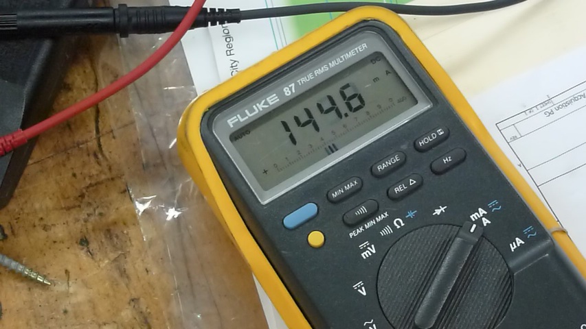
| Open Mesh OM5P-AN Access Point Normal Current Draw | |
| This shows the normal current draw of the Open Mesh OM5P-AN Access Point radio from bootup to normal operational load of Ethernet to roboRIO, Ethernet to IP camera (running 30 fps at 640x, 50% compression), and wireless to a netbook w/Driver station application. |
|
|
Voltage display is in mA
2016 OM5P-AN Access Point 852x480 (.mov, 87 MB) |
|
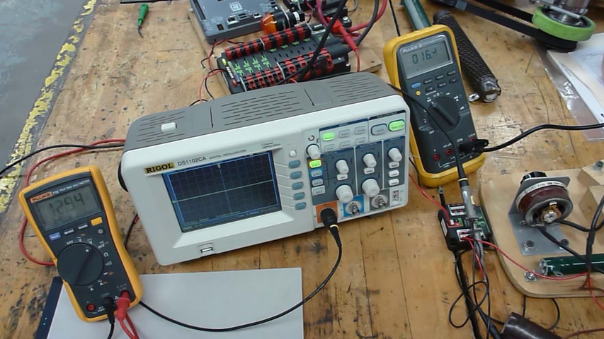
| VRM 12v Overcurrent Clamp at 2.9a - Stress Testing | |
|
Continuous rating for both VRM 5v and 12v outputs are ~1.5a.
2a is the spec momentary peak limit. So, normally the 2016 VRM tolerates over current up to between 2.45a-2.9a before the current is simply cut off. Power to the VRM must be cycled to reset the clamp. This particular run allowed the current to run up to 2.9a before the VRM clamped down. |
|
|
Input voltage display on the left/current amps displayed on scope and on the the right multimeter
2016 VRM 12v Overcurrent Clamp 852x480 (.mov, 26 MB) |
|
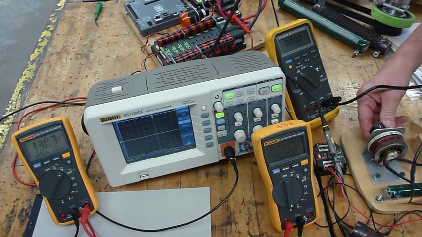
| VRM 12v Overcurrent Clamp at 2.8a - Stress Testing | |
| This run clamped over current at 2.8a. |
|
|
Input voltage display on the left/current amps displayed on scope and on the the right multimeter
2016 VRM 12v Overcurrent Clamp 852x480 (.mov, 32 MB) |
|
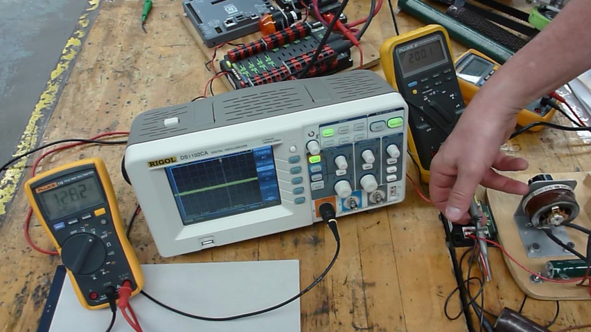
| VRM 12v Overcurrent Clamp at 2.45a - Stress Testing | |
| This run clamped over current at 2.45a. |
|
|
Input voltage display on the left/current amps displayed on scope and on the the right multimeter
2016 VRM 12v Overcurrent Clamp 852x480 (.mov, 25 MB) |
|
| VRM Low Voltage - Stress Testing | |
| This run maintained a load while the input voltage gradually dropped until the VRM output tapered off around the 4v mark. |
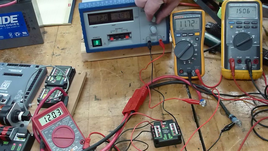
|
|
(left to right) Input voltage to the VRM display on the left, then digital power supply showing the supply voltage and current, next are the amps drawn by the artificial load placed on the VRM output, and finally the VRM output voltage is displayed on the the far right multimeter
2016 VRM Low Voltage 852x480 (.mov, 65 MB) |
|

