Upcoming Events:
Error 406 - Not Acceptable
Generally a 406 error is caused because a request has been blocked by Mod Security. If you believe that your request has been blocked by mistake please contact the web site owner.
Full event list
Error 406 - Not Acceptable
Generally a 406 error is caused because a request has been blocked by Mod Security. If you believe that your request has been blocked by mistake please contact the web site owner.
FIRST® Robotics Competition (FRC®)
2015 roboRIO Control System
Control System 2015-2021

Shortcuts
- System Components
roboRIO | Power Distribution Panel | Voltage Regulator Module | Pneumatics Control Module | Victor SPX Motor Controller | Victor SP Motor Controller | Talon SRX Motor Controller | Spark Motor Controller | Nidec Brushless Motor |
- Other System Components
HiTec Servo | Driver Station | Securing Your Driver Station | Joysticks | Launchpad (2015) | Launchpad (2014) | Cypress I/O | WiFi | RSL | Main Breaker | Breakers | Battery |
- Sensors:
USB Camera | IP Camera | Camera Gimbal | Gyro | Accelerometer | Potentometer | Pressure Switch | Limit Switch | Ultrasonic |
- Discontinued System Components
Jaguar | Victor | Talon | Spike
2018 LabVIEW Examples
- For LabVIEW programmers here are how to do some common LabVIEW robot operations
Beta Testing
|
Hardware Components
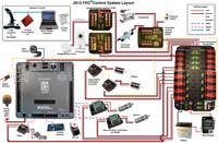
Note: a higher resolution poster-sized layout schematic is FRC roboRIO Wiring Diagram (4140x2722)
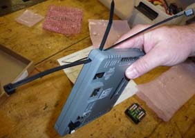
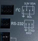
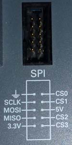
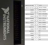
roboRIODesigned and produced by National Instruments
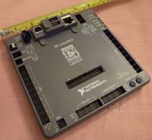
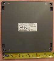
roboRIO dimensions and CAD Performance Notes:
Things you might want to add on your own:
roboRIO source ($435): AndyMark |
Weidmuller Connectors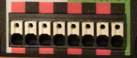 Those little wire terminals on all the new components.
 The small connectors for CAN on the roboRIO and CAN/circuit on the other three new components:PDP,PCM,VRM- are Wiedmuller LSF-SMT Series.
They accept wire gauges of 16-24 AWG. Strip the wire end so that when inserted the insulation is enclosed by the cover. To use with stranded wire hold the white button while inserting or removing the wire.
Notes:
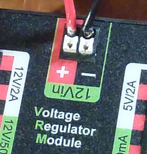
Video showing proper use (fast-forward to proper stranded wire use shown halfway through this video) Good Wiring vs Bad WiringHere's an example of using the terminals properly vs improperly. Good termination (left) will not show any visible wire. The Bad photo (right) shows how wire strands have pushed up and bunched around the top from being pushing them into the terminal. With a little robot rattling or being pulled to the side, these Bad terminals will easily short circuit.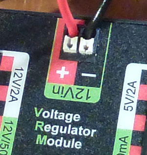
|
Power Distribution Panel (PDP)Designed and produced by Cross the Road Electronics (CTRE) for FRC, this replaces the previous PDP.The PDP does NOT control it's outputs in any way, but it does monitor them for current, battery voltage. Note: Inductive loads (compressor, motors, etc.) should not be connected directly to the PDP, they should always be connected through a control device (Spike, PCM or motor controller). When a motor is connected directly to the PDP, the flyback that may occur during a breaker trip or simply from hot connecting the load may cause damage to the current sense IC's inside the PDP. For instance, the Spike has a suppression diode at the motor terminals to clamp the inductive flyback that happens during both the freewheeling period and direction changes. This also protects the PDP current monitoring circuits. 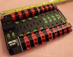
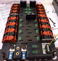
Performance Notes:
Power Distribution Panel source ($200): AndyMark |
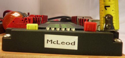
Good Fuses vs Bad FusesTurns out that most folks at competition don't realize just how hard the Two PDP fuses (not the breakers) have to be pressed in before they are seated. Pressed in far enough and you'll feel them snap into place. If they are properly inserted, then they are impossible to remove by hand.Left loose and your robot will die or sputter as the fuses rattle loose. Here are some examples. The first shows properly seated fuses. At least a third of the plastic case should be inside the PDP fuse slots. The second shows one of the fuses as most teams insert them (you can even see the bare metal of the prongs). 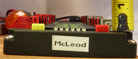
|
Voltage Regulator Module (VRM)Designed and produced by Cross the Road Electronics (CTRE) for FRC, this replaces the 12v/5v regulator and special protected and un-protected power outputs on the old PDP.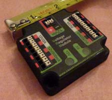
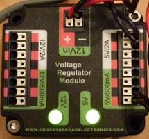
Used for additional components that require special protected power, e.g., wireless bridge, camera, sensors. The power output is protected from battery voltage fluctuations and maintains a steady 12v & 5v for electronics sensitive to supply dips. There are two independent power supplies in the VRM, one 5v and one 12v and each protects itself against continuous power draws above ~1.5a and peaks momentary currents above 2a. Each of these two power rails also incorporate a current limiter of .5a for two sets of terminals, such that a short on a .5a connection will not affect the corresponding 2a connection, however, a short on a 2a terminal will also shutdown the .5a circuit. Note: the 5v rail has just enough power to run both the robot radio (peak 725ma) and one Axis M1011 camera (peak 1.3a) for a combined peak of 2.025a for a short period of time. The 2a outputs are rated for 2a peak only, not continuous, but it is a total 2a between the combined 2a/.5a outputs.
|
Pneumatics Control Module (PCM)Designed and produced by Cross the Road Electronics (CTRE) for FRC, this replaces the previous cRIO solenoid module and breakout.(optional) only required if pneumatics are used. Provides automatic closed loop for control of compressor according to pressure sensor state. 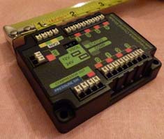
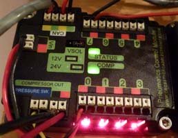
Pneumatics Control Module source ($90): AndyMark |
Wireless2017 Version-OM5P-AC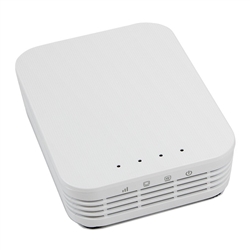
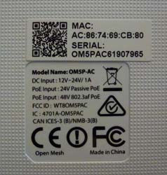
The best orientation to mount the radio in on the robot is horizontally away from metal and sources of electronic RF noise, such as the VRM and battery. The antennas are positioned along the edges of the case (the three sides without the connectors). So mounting this radio horizontally will maximize the antenna radiation in the horizontal plane of the playing field. In 2017 the AN model has been superceeded by an almost identical AC model. This one has a completely flat top and vents only on the sides, not on the bottom, allowing for easier and more varied mounting options. 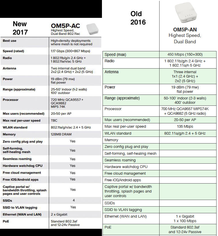
Both of these radios can be powered either by a barrel connector and/or a passive POE injector, but the 12v power required should come from a competition legal VRM. In fact, for redundant power you can connect both POE and a barrel connector 12v power, if one flickers the other takes over preventing and avoiding a time consuming radio reboot. 
WARNING: This is a 12 volt device (unlike the old DLink) and requires the use of the VRM 12v/2a power for use on the competition robot. 2016 Version-OM5P-ANBoth the OpenMesh OM5P-AC, and the discontinued OpenMesh OM5P-AN can be used in competition. This is the older OpenMesh OM5P-AN Access Point: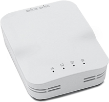
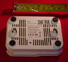
Source: Open Mesh OM5P-AC Access Point Note: A special price is available for FRC teams when they sign-in through their team account at AndyMark. |
Victor SPXThe Victor SPX is a motor controller directed via either PWM or CAN introduced for the 2018 competition season.developed by VexPro & Cross the Road Electronics (CTRE) 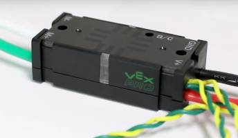
Selections from the technical specs :
Brake mode (red light on), Coast mode (red light off), Calibration mode (status lights alternating blinking-followed by flashing red indicating calibration failure) To switch between Brake/Coast momentarily push the Brake/Coast/Calibrate button. The button is illuminated red when the Victor-SP is in Brake mode and un-illuminated when in Coast. To calibrate, hold the button until the the status LEDs (the LEDs on the sides) begin to rapidly blink between red and green. While continuing to hold the button, move the joystick to full forward then to full reverse. This can be repeated if desired. Allow the joystick to return to neutral then release the button. If the calibration succeeded you should see the Status LEDs blink green, if it failed they will blink red. To restore default calibration, with the controller unpowered, press and hold the button while applying power to the controller until the status LEDs blink green. Specs: Victor SPX source ($50): Vex Robotics |
Victor SPThe Victor SP is a motor controller directed only via PWM.developed by VexPro & Cross the Road Electronics (CTRE) 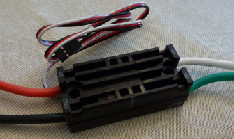


Selections from the technical specs :
Video demonstrating: 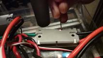 Brake mode (red light on), Coast mode (red light off), Calibration mode (status lights alternating blinking-followed by flashing red indicating calibration failure)
To switch between Brake/Coast momentarily push the Brake/Coast/Calibrate button. The button is illuminated red when the Victor-SP is in Brake mode and un-illuminated when in Coast. To calibrate, hold the button until the the status LEDs (the LEDs on the sides) begin to rapidly blink between red and green. While continuing to hold the button, move the joystick to full forward then to full reverse. This can be repeated if desired. Allow the joystick to return to neutral then release the button. If the calibration succeeded you should see the Status LEDs blink green, if it failed they will blink red. To restore default calibration, with the controller unpowered, press and hold the button while applying power to the controller until the status LEDs blink green. Victor SP source ($60): Vex Robotics |
Talon SRXThe Talon SRX, is a CAN enabled motor controller with CAN, SPI, Digital IO, and USART (serial) communication protocols and a variety of internal control modes inluding feedback PID. Available at VexPro & Cross the Road Electronics (CTRE) 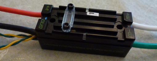
Selections from the technical specs :
Talon SRX source ($80): Vex Robotics |
Spark MAX motor controllerREV Robotics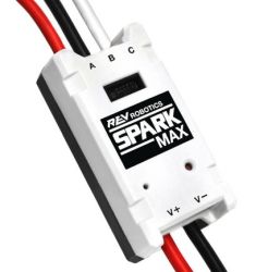
This unique smart motor controller can drive either standard brushed motors or the Rev Neo brushless motor via PWM or CAN control. It also has a USB interfacethat can be used to set configuration parameters. It also offers a USB interface for control and configuration.
Spark MAX source ($75): REV Robotics |
NEO Brushless MotorREV Robotics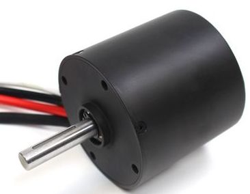
This Rev Neo brushless motor requires a SparkMAX motor controller to operate.
Neo source ($40): REV Robotics |
SparkREV Robotics has a modern motor controller called a Spark.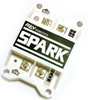
60A continuous current with passive cooling, bi-directional limit switch inputs for smart mechanism control, an RGB LED status indicator, and a button-activated brake/coast mode. Special Note: When the SPARK is not receiving a PWM signal (robot Disabled or PWM disconnected) it temporarily reverts to coast mode, no matter what the button setting is. Selections from the technical specs :
Spark source ($45): Amazon & REV Robotics |
Nidec Brushless MotorIt may seem odd to find a motor listed here under Control System, but that's because this brushless motor comes integrated with a new motor controller.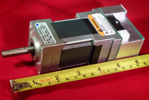
This is a brushless motor (a first for FRC) that combines a motor, speed controller, and tach/direction feedback.
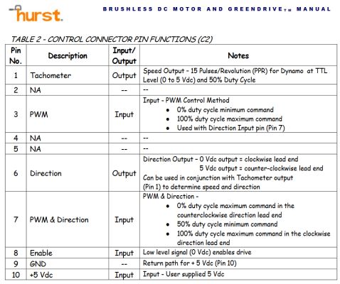
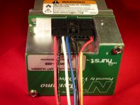
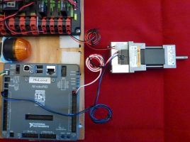
Wiring Connections:
There is a caution with the brushless wiring. **** If the DIO connection comes loose, then the motor will race uncontrollably while the robot is Enabled. **** It is designed to be disabled when the robot is disabled, so it can be quickly halted if this happens. But remember that if it happens during a match, then the only way to Disable the runaway motor is by eStop and your role in the match is over. Consider your application carefully to account for this possibility. A racing beater bar isn't a problem, but a racing gripper might burn out the motor or damage the mechanism. You can program in a safety override to disable the motor with a button, or to automatically disable the motor whenever it's in neutral. Note also that the integrated tachometer does not operate while the motor is disabled. Nidec Brushless Motor source ($99): AndyMark |
Automation Direct Solid State Relays Automation Direct Solid State Relays They are on/off, single direction relays good for motors, lights, or special circuits. 12v power comes from a PDP Wago output, using appropriately sized wiring, and the power inputs are reverse polarity protected. The control typically connects to a roboRIO relay output, but can also be connected to a (DIO) Digital output. This relay is legal for FRC use beginning in 2019. 12a, 25a, or 40a versions are FRC legal (momentary surge peaks of 27a/50a/90a respectively). Metric terminal screws. 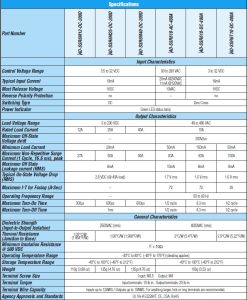 Specs Specific part numbers only: Relay source ($17-$40):
|
Support & Discontinued (but still legal) Components
Other control system components include:- Victor/Jaguar/Talon speed controllers (out of production)
- Spike Relay
- Robot Status Light
- Laptop Driver Station
- Wireless
Speed Controller-JaguarNote: This model has been discontinued 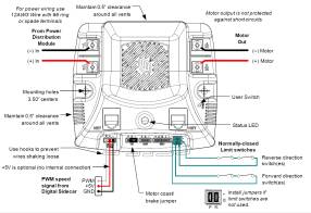
One Page Intro., Jaguar Getting Started
cRIO Jaguar PWM specs (and test measurements using a run-of-the-mill digital voltmeter):
The Jaguar provides smoother control and is especially valuable at fine-tuned low speed control and it self-protects against over-current/temp. The Victor can handle some higher current stress for longer periods of time, but in a severe over-current case it would fail catastrophically. There are also reports of the Jaguar not working well with the Denso window motors. In any case new applications should be throughly tested to see which speed controller is more appropriate. Fault ConditionsA slow flashing Red LED indicates that the MDL-BDC detected one of the following fault conditions:
When a fault condition occurs, the motor shuts down and the LED indicates a fault state during the fault condition and for 3 seconds after the fault cause is cleared (except for the limit switch fault, which is cleared instantly). A slow flashing Yellow LED indicates that the MDL-BDC is not receiving a valid control signal. CALIBRATION PROCEDURETo calibrate the servo-style PWM input for a specific range, connect a PWM source, then:
The MDL-BDC samples these signals and centers the speed range and neutral position between these limits. A calibration failure will be signaled if an out-of-range signal is detected. To reset the servo-style PWM input to the default factory range:
To use a CAN interface with the Jaguar, see the Jaguar Getting Started document for CAN wiring instructions. In addition, the roboRIO no longer uses the RS232 port for CAN communications, so the wiring for the first Jaguar in a CAN chain just requires that the two CAN wires be connected to one of the PDP CAN ports. Note: FIRST software support for Jaguar CAN has been dropped as of the 2018 season. Source: Discontinued |
Speed Controller-VictorNote: This model has been discontinued This has been around longer than the Jaguar and has different characteristics. The Victor allows high current for longer than the Jaguar, while the Jaguar permits finer control. The Jaguar also does not seem to work well with the Window motors under certain circumstances, causing the Window motors to heat up unusually and be shutdown by the Window motor's thermal overload protection. The Victor has improved models over the years (883/884/888), and the current model 888 have improved response. 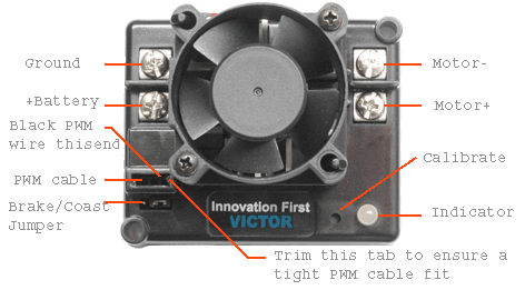
Victor 888 Speed Controller User Manual
cRIO victor PWM specs (and test measurements using a run-of-the-mill digital voltmeter):
Source: Discontinued |
Speed Controller-TalonNote: These models (Talon & Talon SR) have been discontinued Brushed DC motor speed control featuring a sealed design with passive cooling and a footprint slightly smaller than a Victor. Without the optional fan it is also much shorter. From Cross the road electronics 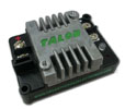
Source: Discontinued |
Spike Relay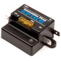
Note: The Spike Relay has been discontinued The Spike is not a PWM device although it is controlled by a PWM-style cable. It can not be connected to an R/C hobby type receiver. The Spike is designed to plug into special Relay Ports.
Source: discontinued |
HiTec Servo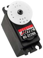
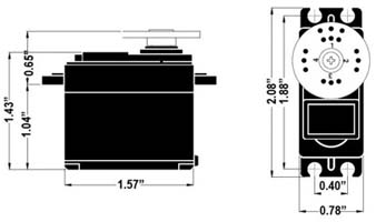
The HiTec servo is a small motor that can be commanded to rotate to a particular position in a range of ~270 degrees. It has a varied of "horns" or the white part in the accompanying photo that are interchangeable, and are often used with homegrown mechanical linkages to increase their effectiveness. This attaches to the roboRIO PWM outputs and is powered by the 6v power from the PWM connection, 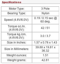
Source: AndyMark |
Driver Station (DS) ApplicationFirst, The Driver station is really a custom FRC application that can be run on most Windows OS's The Driver Station application is closed source to secure dependable robot safety protocols and must be used by all teams to compete. The Driver Station provides feedback on PC to robot communications (overall and ping statuses for components in the network).


A companion application called the Dashboard can be created by the team from tools provided by FIRST or completely generated on their own. A fully operational and comprehensive default Dashboard LabVIEW application comes from FIRST, which can be used as-is, modified, replaced completely, or eliminated, as the team desires. The default Dashboard provides:
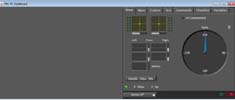


Driver Station (DS) (2012/2013/2014/2015 version) HardwareFRC provides teams starting out with a rugged low-end netbook called a Classmate to serve as host to the Driver Station software. It has enough power to support all the basic Driver Station and Dashboard operations. 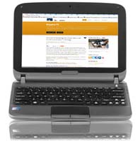 Any laptop is now legal with only the Driver station application a requirement.
Rookies are still provided with a Classmate. FIRST provides new (optional) Classmate images to update older Classmates to Windows 7 (if necessary) and pre-install the current year's programming environment(s). The oldest E09 only installs the Driver Station, because the very limited disk space does not leave enough room for today's larger programming tools. 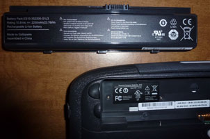 It is important to install the proper image for the model Classmate. The wrong image will give you an operational netbook, but the drivers will be incorrect. Usually the first indication that the wrong image was loaded is that the video appears stretched and is limited to 800x600 or 640x480 rather than the normal 1024x600.
You can find the Classmate model number inside the battery compartment. A rolling press of all three [ ] \ keys will Enable the robot Enter key = Disable robot The 2012/13/14 Classmate power adaptor produces 2.1 amps @ 19v with center positive on the barrel connector. 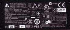
Classmate E12 Specs Any laptop is legal. Only the FRC Driver Station application is required. |
Safe, Secure Driver Station Laptop Operation:
|
Joysticks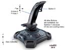
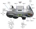
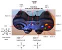
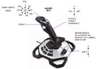
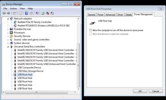
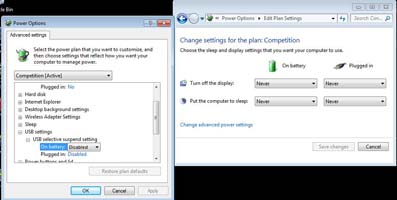
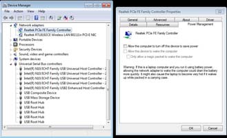
Logitech Attack 3, xBox 360, Logitech F310 (mapping changes for a Dual Action/xBox Emulator switch on bottom and for a Sports mode switch on top) Extreme 3D Pro (click on game controllers for 2015 FRC mapping of buttons & axes) To control the robot the Kit of Parts includes the classic Attack3 Joystick and others through FIRST Choice or the physical kit. Any USB wired game controller can be used, such as Xbox 360 or Playstation 3 USB compatible game controllers. It just has to be recognizable by the Windows OS with an appropriate hardware driver on the Driver Station laptop as a game controller. Non-game controllers such as keypads are not recognized by the Driver station application. Note: Some game controllers (like the F310 above) have mode buttons and switches that change how the buttons and axes are mapped. This can inadvertently lead to a mysterious loss of control if the driver hits the button/switch accidentally. Controllers without such a switch are more foolproof to use. Warning: power hungry controllers and loaded down USB hubs may brown out during competition. Basic controllers connected directly to the laptop USB ports with power saving turned off are safest. When the driver station is running on laptop battery it begins to cut power to USB ports starting with the ports with the highest power drain. Usually, that means starting with ports connected to bigger drain USB hubs that have several devices hanging off them, or LED heavy game controllers. Changing Windows USB Power Settings Source: Game console retailers like Best Buy, GameStop, Target, Walmart |
Texas Instruments MSP430 Launchpad (2015)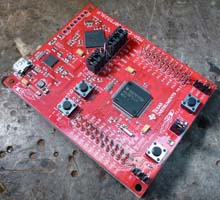
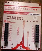
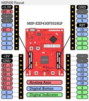 The Launchpad requires custom firmware provided by TI to set it up to behave like a standard HID joystick (or two joysticks), making buttons and dials available for user custom designed control board extensions.
The board itself is powered by and communicates through a USB connection to the laptop/netbook running the Driver Station application. A Gamepad Tool to setup the board is included as part of the FRC Update package (where the Driver Station comes from too). Several optional pinout setups are available through the Gamepad Tool. Directions and further information/help is provided by the TI wiki: MSP430 LaunchPad Operator Interface for FIRST Robotics Competition MSP430 Gamepad code Source: TI Store |
Texas Instruments Stellaris Launchpad Evaluation Kit LM4F120 (2014)

The Stellaris requires custom firmware provided by TI to set it up to behave like a standard HID joystick (or two joysticks), making buttons and dials available for user custom designed control board extensions. The unit is stackable with other breakout boards to add capability or simplify screw terminal connections. The Stellaris is powered by and communicates through a USB connection to the laptop/netbook running the Driver Station application. User Manual Using the Stellaris LaunchPad in FRC Source: Digikey |
Cypress CY8CKIT-049-42xx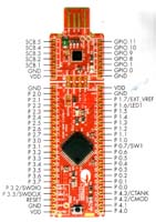
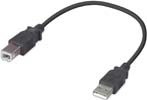
This year's version of the Cypress demo board can be used for driver station buttons and potentiometers. One end of the board itself is a USB connector that can be plugged directly into a laptop, but it needs to be supported somehow. It can also connect to a standard A/A USB cable that then plugs into the laptop making a somewhat more secure connection. The board has through holes where wires must be soldered to make use of the connections you want. Additional information is at: Cypress CY8CKIT-049-42xx |
Rockwell Robot Status LightPart #: 855PB-B12ME522 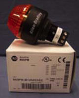
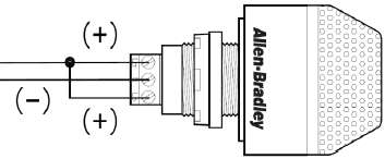

This is an LED light that only pulls 62mA (12v), but is quite bright. Wired one way it will flash forever, but wired correctly it will repeat exactly what the RSL LED on the roboRIO does. Ground, Power and most importantly-a jumper MUST be used. RSL Wiring The RSL blink pattern tells what state the robot is in. The patterns can be changed year-to-year but in 2015 they are:
|
Main Breaker/Robot Power Switch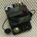
The battery connects through Anderson connectors to this 120 amp breaker used as the main robot power switch. It is very unlikely that this will ever trip under normal conditions as it withstands amperage much greater than 120a for some period of time before tripping. If it does trip you have a serious electrical problem, or ill designed overloaded power draws.
120amp Main Breaker/Robot Power Switch Spec. Source: AndyMark |
Snap Action Breakers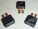
These mount in the Power Distribution Panel and are self-resetting 40/30/20 amp breakers for individual circuit protection. It's important to remember that these only safeguard the wiring, and it's critical that they each be used with the properly rated wire gauge (or better). They do not protect devices like the speed controllers. Snap-Action 30/20a Breaker Spec. Snap-Action 40a Breaker Spec. Source: VexPro or AndyMark |
EnerSys NP18-12 or MK ES17-12 Batteries FRC robots are restricted to specific 12v batteries approved by FIRST for competition.
FIRST greatly expanded the list of approved battery models and has been willing to consider approving different models, but direct communication with FIRST including battery specs are required.
All battery models used in competition must appear on an approved FIRST list checked by inspectors.
One or two batteries are provided in the Kit and if they are the same past years batteries can be used as spares.
It's a good idea to have several (4-5) batteries (and chargers) for competition.
Specs: EnerSys NP18-12 Datasheet MK ES17-12 Datasheet Material Safety Data Sheet (MSDS): EnerSys NP18-12 MSDS Source: AndyMark |
Sensors
The choice of sensors is generally wide open. These are sensors that have appeared in the KOP in past years or that are commonly encountered on FRC robots. FIRST generally places only a few rules restrictions on sensors, such as limitations on potentially hazardous higher powered laser-based sensors and a $400 max price per unit.
FRC 2011 Sensor Manual
USB Cameras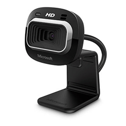 Any USB camera will work with the roboRIO that is
Linux UVC compatible (there's a list of compatible USB cameras at that link).
We tested both the Microsoft HD3000 LifeCam (shown) and the Logitech HD Pro Webcam C920 on the roboRIO. Since it is a USB device connected directly to the roboRIO you must have user code to process and/or forward the video stream to the Dashboard for viewing. Source: AndyMark |
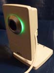
Axis 206/M1011/M1013 Webcam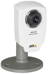 This optional network camera is connected through the DLink network bridge (any cable/camera model). For the default camera code to work with it there must be a special user account - username: FRC/password: FRC
Note: the screw mount on the camera back takes an M4 metric nut. The power plug is size H: Tip size: 3.4mm O.D.x1.3mm I.D. 

Camera Image Compression vs. image file size
Source: AndyMark Camera Gimbal (aka, Pan & Tilt Assembly)
If your camera use calls for searching for targets where a fixed mounting position is inappropriate, then something like this can be purchased through AndyMark Camera Pan and Tilt Assembly Diagrams |
Kit GyroscopeAnalog Devices ADW22307 1-axis Analog Gyroscope 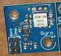
Accelerometer-Gyro Guide Wire to analog input:
The gyro positive direct is shown on the board. The second triplet of pins returns temperature (not commonly used). FRC Gyroscope Specs |
Kit AccelerometerAnalog Devices ADXL345 3-axis Digital Accelerometer. 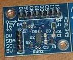
Maximum of 250 degrees per second for the Analog Devices ADW22307. Nominal output is 2.5V at standstill, plus 7mV/¡/s. This connects to either the roboRIO SPI or I2C communication ports. SPI output (J4): wire to Digital I/O pins on the roboRIO
The alternate I2C output (J2): wire to the pins on the roboRIO found next to the input power connector. By default, the I2C address of this accelerometer board is 0x3A. The address can be changed to 0xA6 by shorting J1 with a blob of solder.
FRC Accelerometer Specs |
Pneumatic Pressure Sensor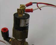
The pressure switch sensor is used as part of the pneumatic sub-system. It tells the controller when to turn the compressor on as the air pressure drops, and when to turn it off as pressure reaches maximum. It connects to a specific reserved input on the PCM. The terminals are interchangable.
Spec: Nason Pressure Switch |
Potentometer
Potentiometers (or "pots") in robotics are most frequently coupled to a mechanism to measure the angle of rotation or a distance of mechanism travel. It is a simple analog device that's a little noisy, so doesn't return an exact value and has a certain amount of flicker in it's readings. Think of a volume control knob (avoid "audio tapers" for robotics use though) or a light dimmer. Pots come in several useful varieties:
They have three terminals:
The voltage divider (used when connected as a cRIO Analog input) uses all three terminals. The variable resistor only requires the ground and signal terminals. Source: Radio Shack (search for "potentiometer") |
Limit Switch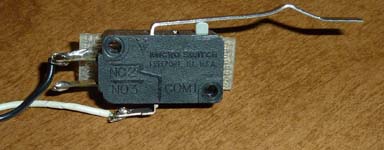
Limit switches are intended to be pressed by some mechanical mechanism to signal a stop or limit of movement. The switch connects to a roboRIO digital input and is marked on the side with a simple wiring diagram.
Normally Open is how most people typically think of switches operating. There are two wiring options. The switch only requires two connections:
FRC Limit Switch Spec Source: Radio Shack (search for "SPDT switch") |
Defunct components
pre-2016 Wireless
In 2016 the D-Link DAP-1522 Rev B AP/bridge has been discontinued.
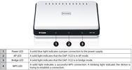
WARNING: This is a 5 volt device and requires the use of the VRM or similar 5v/2a power for use on a non-competition robot.
Source: Discontinued
D-Link DAP-1522 Rev B manual (2012)
D-Link DAP-1522 Rev B Firmware for FRC (2012)


